
Understanding how do inertial measurement units work helps you grasp the technology behind drones, smartphones, vehicles, and advanced robotics. An inertial measurement unit, or IMU, measures motion using internal sensors that detect acceleration and rotation in three dimensions.
Understanding how these sensors interact and how data is processed provides insight into modern navigation, decision-making systems, and high-performance control platforms. Keep reading to get more information.
What Is an Inertial Measurement Unit?
An inertial measurement unit is an electronic device that measures linear acceleration and angular velocity along three orthogonal axes. You typically find an IMU built around a three-axis accelerometer and a three-axis gyroscope, with many systems also including a magnetometer. Together, these sensors allow you to track motion, orientation, and position changes without relying solely on external references.
You rely on IMUs in systems where GPS signals may drop or where precise short-term motion tracking is critical. Aircraft, autonomous vehicles, wearable devices, and industrial monitoring systems all use IMUs to maintain stability and situational awareness. The IMU acts as the core motion-sensing component that feeds data into higher-level control and navigation algorithms.
Modern IMUs are compact because they use microelectromechanical systems (MEMS). This miniaturization allows you to embed motion intelligence into small devices without sacrificing reliability. As a result, IMUs have become standard components in consumer electronics and advanced aerospace systems alike.
The Core Sensors Inside an IMU
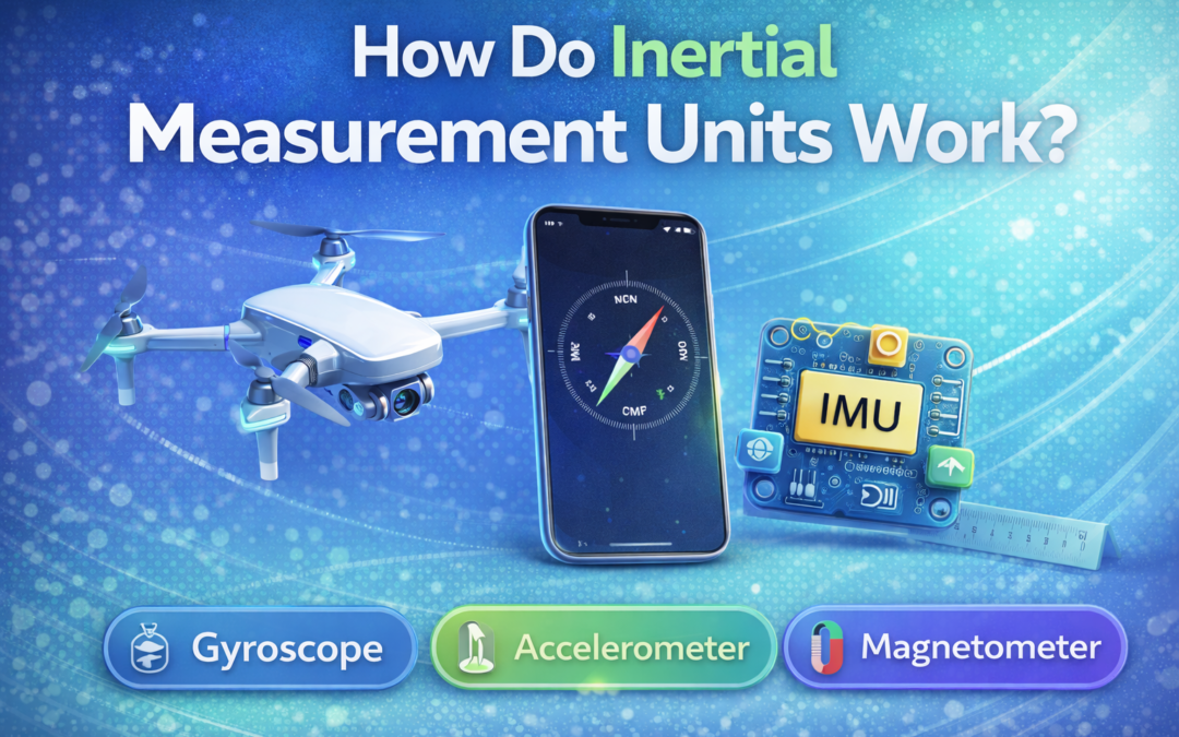
To understand how do inertial measurement units work, you must first understand their internal sensors. The three primary sensors are accelerometers, gyroscopes, and sometimes magnetometers. Each one measures a different physical phenomenon, and together they create a complete picture of motion.
An accelerometer measures linear acceleration along the X, Y, and Z axes. A gyroscope measures angular velocity, which tells you how fast the device is rotating around each axis. A magnetometer measures the surrounding magnetic field, helping you determine orientation relative to Earth’s magnetic north.
When these sensors operate together, they provide six or nine degrees of freedom, depending on configuration. A six-axis IMU combines a three-axis accelerometer and a three-axis gyroscope. A nine-axis IMU adds a three-axis magnetometer, enabling more accurate heading estimation and orientation tracking.
How Accelerometers Measure Linear Motion
Accelerometers inside an IMU often use MEMS structures composed of a tiny proof mass suspended by micro-scale springs. When the device accelerates, inertia causes the proof mass to shift relative to its frame. This displacement changes the sensor’s capacitance, and the electronics convert that change into a measurable voltage.
You can interpret the voltage output as acceleration in meters per second squared. Because the accelerometer measures acceleration along three axes, you can detect forward movement, lateral motion, and vertical displacement. The accelerometer also senses gravity, which allows you to estimate tilt relative to the Earth’s surface.
In practical systems, accelerometers detect vibration, shock, and dynamic motion. They help stabilize drones, monitor structural health, and measure human movement in wearable devices. By analyzing acceleration data over time, you can estimate velocity and position, although this process introduces cumulative error if left uncorrected.
How Gyroscopes Detect Rotation
Gyroscopes in modern IMUs typically rely on the Coriolis effect within a vibrating MEMS structure. When the device rotates, the vibrating mass experiences a force perpendicular to its motion. This force creates a measurable deflection that corresponds to angular velocity.
You measure angular velocity in degrees per second or radians per second. The gyroscope tells you how quickly the device rotates around each axis, enabling precise tracking of orientation changes. This information is critical in aerospace systems, robotics, and automotive stability control.
However, gyroscopes are prone to drift over time. Small measurement errors accumulate when integrating angular velocity to calculate orientation, leading to a gradual deviation from the true value. That is why you must combine gyroscope data with other sensor inputs to maintain long-term accuracy.
The Role of Magnetometers and Heading
A magnetometer measures the strength and direction of the magnetic field surrounding it. In most applications, you use it to determine heading relative to Earth’s magnetic north. This function allows you to correct gyroscope drift and maintain stable orientation estimates.
Magnetometers rely on sensing principles such as the Hall effect or magneto-resistive elements. They detect tiny variations in magnetic flux and convert them into electrical signals. When calibrated properly, they provide reliable compass-like functionality within an IMU.
You must account for magnetic interference from nearby electronics or metal structures. Calibration routines compensate for distortions and bias to maintain accurate heading information. When integrated into a nine-axis IMU, the magnetometer enhances overall orientation stability.
Sensor Fusion and Drift Correction
Sensor fusion is the process of combining accelerometer, gyroscope, and magnetometer data to produce a stable estimate of orientation and motion. Algorithms such as the Kalman filter or complementary filters continuously adjust estimates based on sensor strengths and weaknesses. This approach reduces drift and improves long-term accuracy.
For example, the gyroscope provides smooth short-term rotation data, while the accelerometer helps correct tilt based on gravity. The magnetometer corrects heading relative to Earth’s field, reducing cumulative yaw error. Together, these sensors form an attitude and heading reference system, often abbreviated as AHRS.
If you integrate acceleration twice to calculate position, even tiny biases can create large-scale errors over time. That is why IMUs are often combined with GPS or external references in navigation systems. The fusion process ensures reliable motion tracking even in dynamic environments.
Understanding IMU Specifications
When selecting an IMU, you must evaluate the range, resolution, and scale-factor error. Range defines the maximum measurable acceleration or angular velocity, such as ±2 g or ±2000 degrees per second. Resolution determines the smallest detectable change in input.
A narrower measurement range often yields higher resolution, thereby improving precision in sensitive applications. However, if your system experiences high acceleration, you need a wider range to prevent saturation. If you sanity-check calibration masses across unit systems, how many ounces in 100 grams helps you keep conversions consistent without rounding guesswork.
Temperature stability also affects accuracy. When your workflow includes frequent unit conversions for test weights, convert grams to ounces keeps your calibration notes aligned with the values you log in your sensor reports. Many IMUs include internal temperature sensors to compensate for thermal drift, which improves repeatability across changing environments.
MEMS vs Fiber-Optic Gyroscopes
Most consumer and industrial IMUs rely on MEMS technology because it offers compact size and low cost. MEMS devices provide sufficient accuracy for smartphones, drones, and automotive systems. They also consume less power, making them ideal for battery-operated platforms.
In high-precision aerospace or defense applications, you may encounter fiber-optic gyroscopes. These systems measure rotation using interference patterns of light traveling through an optical fiber. They offer extremely low drift and high stability, but they are larger and more expensive.
Your selection depends on size, weight, power, and cost constraints. MEMS-based IMUs dominate mass-market applications, while fiber-optic solutions serve specialized high-accuracy environments. Understanding these trade-offs helps you choose the right motion-sensing technology.
Applications Across Industries
IMUs play a central role in aviation, automotive systems, robotics, and consumer electronics. In autonomous vehicles, they provide real-time orientation data that supports lane-keeping and stability control. In drones, they maintain flight stability and enable precise maneuvering.
You also find IMUs in smartphones for screen rotation, gesture recognition, and augmented reality features. Industrial systems use IMUs for vibration monitoring and predictive maintenance. In many industries, IMU data is valuable because it provides continuous motion awareness even when external tracking systems fail.
Measurement literacy strengthens how you interpret sensor outputs and calibration tables. If you ever need a quick perspective on unit standards during documentation, is ounces metric clarifies where ounces fit when you compare metric and imperial conventions. Clear unit handling reduces mistakes when you report ranges, tolerances, and test results.
IMUs and Navigation Systems
An IMU alone measures motion relative to itself, but it becomes more powerful when integrated into an inertial navigation system. By combining IMU data with GPS and external references, you can estimate position, velocity, and attitude in real time. This integration allows reliable navigation even when satellite signals drop temporarily.
In aviation and marine systems, inertial navigation ensures continuous tracking in challenging environments. Military and commercial aircraft rely on these systems for stable flight control and situational awareness. Autonomous vehicles similarly depend on IMU-GPS fusion to maintain accurate localization.
You must recognize that inertial navigation depends on precise data processing. Any bias in acceleration or rotation measurement compounds over time, reinforcing the importance of calibration and sensor fusion. Robust algorithms transform raw sensor readings into actionable navigation insights.
Real-World Example of IMU Data Interpretation
Imagine you are designing a drone stabilization system. The accelerometer detects sudden vertical movement, the gyroscope measures pitch and roll changes, and the magnetometer stabilizes heading. The flight controller processes this data within milliseconds to maintain level flight.
If the drone experiences wind gusts, the gyroscope immediately detects rotational changes. The control system adjusts motor speeds to counteract rotation and restore balance. This continuous feedback loop shows how IMU signals become control actions in a real system.
You see similar principles in wearable fitness devices that track steps and orientation. Accurate motion sensing depends on proper calibration, filtering, and consistent reference frames. When you tune thresholds and filters, you reduce noise while maintaining high responsiveness.
Conclusion
When you ask how do inertial measurement units work, you are exploring a technology that blends physics, electronics, and advanced algorithms into one compact device. An IMU measures linear acceleration and angular velocity and, through sensor fusion, transforms raw signals into stable orientation and motion estimates. This capability supports navigation systems, autonomous platforms, and everyday consumer electronics.
You now know how accelerometers detect linear motion, how gyroscopes measure rotation, and how magnetometers improve heading stability. You also understand why drift correction, temperature compensation, and specification literacy matter for real-world accuracy. With this foundation, you can evaluate IMU data with more confidence and make better engineering decisions when motion precision matters.